|
|
| |
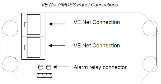
VE.Net GMDSS Panel
Contents of the box
1 x VE.Net GMDSS Panel
4 x Black screw to mount the panel
1 x Panel cutout
1 x Installation and user manual
* Plan de connexion SKYLLA SMDSM 24/30 24/50
* Notice Panneau de contrÙle VE.NET pour SKYLLA SMDSM
* SchÈma d'installation VE.NET GMDSS avec Skylla SMDSM
| VE.Net |
SMDSM Panel |
| Maximum cable length |
25 meter |
| VE.Net GMDSS Panel |
VPN |
| Power supply voltage range |
9 ñ 35 V DC |
| Operating temp. range |
-20 ñ +50∞C (0 - 120∞F) |
| Potential free contact |
3A / 30 V DC / 250 V AC / (Normally closed) |
| ENCLOSURE |
| Measurements front panel (w x h) |
12 x 6,5 cm (Standard PROS3 Panel) |
| Measurements body (w x h) |
10 x 4,5 cm |
| Weight |
0,1 Kg |
|
| |
| Panel Setup |
Default |
Range |
Step
size |
| Contrast |
Contrast of the display |
100 |
0-100% |
5% |
| Backlight |
Intensity of the backlight |
30 |
0-100% |
5% |
| Backlight off |
Time before the backlight turns off automatically |
10s |
10s, 30s,
1 min, Never |
|
|
Access level |
In order to prevent accidental changes to settings, most setup parameters are hidden in user mode |
User and
install |
User,
User
and Install |
|
| Restrict Access |
Disables changing the access level, only possible for OEM installers |
No |
Yes, No |
|
| Restart panel |
Restart the panel |
No |
No-Yes |
|
| Software version |
Version of the software in the panel |
- |
- |
- |
|
| |
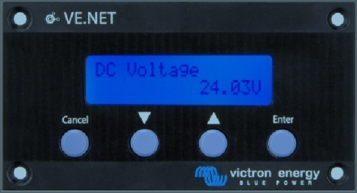
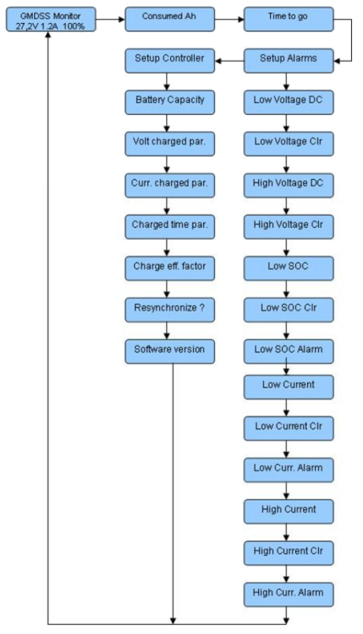
| Quick status |
| DC Voltage |
Displays the actual voltage of the battery. |
| DC Current |
Displays the DC current that flows in or out of the batteries. |
| State of charge |
The state of charge is a representation of the energy left in the battery 100% is full and 0% is empty. This is the best way to see when the batteries need to be recharged. Note that most battery types will be damaged if they are discharged below 50%. |
|
| |
| Read out menu |
| Consumed Ah |
Displays the used ampere hours since the battery was fully charged. |
| Time to go |
Displays time left before the batteries need to be recharged at the current load. |
|
| |
| Setup Alarms |
Default |
Range |
Step
size |
| Low Voltage |
The DC Voltage has to be below this threshold to trigger the Low Voltage alarm.
|
20 |
8 - 33 |
0.1 |
| Low Voltage Clr |
The threshold that has to be reached again to cancel a Low Voltage alarm. |
22 |
8 - 33 |
0.1 |
| High Voltage |
The DC Voltage has to be above this threshold to trigger the High Voltage alarm. |
32 |
8 - 33 |
0.1 |
| High Voltage Clr |
The threshold that has to be reached again to cancel a High Voltage alarm. |
31 |
8 - 33 |
0.1 |
| Low SOC |
The low State of Charge threshold that will activate the alarm. |
60% |
0 - 100 |
1 |
| Low SOC Clr |
The State of Charge threshold that has to be reached to cancel a State of Charge alarm. |
60% |
0 - 100 |
1 |
| Low SOC Alarm |
Enables and disables the low SOC alarm. |
off |
on - off |
|
| Low Current |
The current has to be below threshold to trigger the Low Current alarm. |
-100 |
-100 ý +100 |
0.5 |
| Low Current Clr. |
The threshold that has to be reached again to cancel a Low Current alarm. |
-98 |
-100 - 100 |
0.5 |
| Low Current Alarm |
Enables and disables the low current alarm. |
off |
on-off |
|
| High Current |
The current has to be above this threshold to trigger the High Current alarm. |
35 |
-100 - 100 |
0.5 |
| High Current Clr |
The threshold that has to be reached again to cancel the High Current alarm. |
32 |
-100 - 100 |
0.5 |
| High Current |
Enables and disables the high Current Alarm. |
off |
on - off |
|
|
| |
| Setup Controller |
Default |
Range |
Step
size |
| Battery Capacity |
The battery capacity in amp hours (Ah) at a 20h discharge rate. |
200Ah |
20-65535 |
5 |
| Volt charged par |
The battery controller considers the battery as fully charged if the voltage is above this level. |
26.4V |
8-33 |
0.1 |
| Curr charged par |
If the charge current is below this percentage of the battery capacity, the battery can be considered as fully charged. |
4% |
1-10 |
1 |
| Charged time par |
The minimum time that the above two parameters must be met to consider the battery as fully charged. |
4 min |
1-4 |
1 |
| Charge eff. Factor |
When a battery is charged, energy is lost. The charge efficiency factor compensates for the lost energy, where 1 is no loss of energy and 0.5 is a 50% loss of energy. |
0.9 |
0.5-1 |
0.05 |
| Resynchronize? |
Resets the state of charge manually to 100%. |
- |
- |
- |
|
| |
 |
| |
Exemple d'installation du chargeur SMDSM
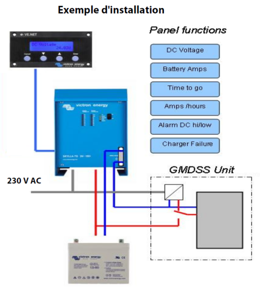
Pas de rÈglages compliquÈs : PrÍt ý raccorder
Le systËme complet est livrÈ prÍt ý raccorder, les tableaux d'affichage sont prÈprogrammÈs pour la fonctionnalitÈ SMDSM. Un menu dÈroulant simple et convivial permet les paramÈtrages spÈcifiques.
|
|
|

.png)